Reciprocating Compressor Testing
The reciprocating compressor testing article provides information about reciprocating compressor mechanical running test, aerodynamic testing, hydrostatic testing, gas leakage test, bar-over test and vibration analysis and testing. You may want to review the reciprocating compressor inspection procedure and inspection and test plan.
Reciprocating Compressor Mechanical Running Test
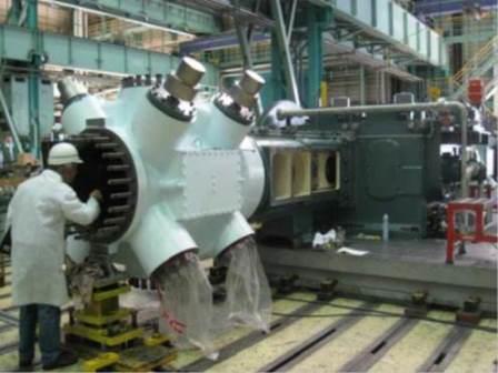
The API Std. 618 requires that reciprocating compressor to be subjected to the 4 hours unloaded running test after successful inspection and testing that are done before and during assembly. To perform an unloaded running test, the reciprocating compressor cylinder valves shall not be installed for the mechanical running test. The mechanical running test is considered a routine test in the reciprocating compressor testing.
The test shall be performed based on manufacturer approved test procedure. The compressor is brought to the rated speed and then runs for 30 minutes to get lube oil temperature, viscosity, bearing temperatures and vibration amplitudes stabilized.After operating parameter stabilization, the test technician records the parameters in each 10 or 15 minutes as per requirements.
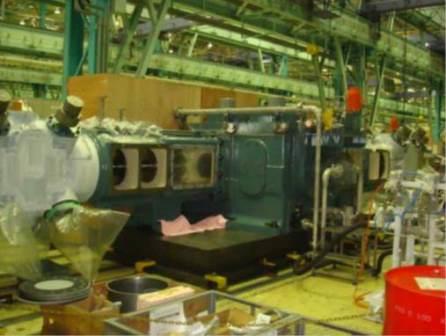
The following parameter is recorded periodically in this 4 hours:
- Lube Oil Pressure
- Lube Oil Temperature
- Bearing Temperature
- Lube Oil Viscosity
- Power Consumption
- Rotor Speed
- Vibration
The recorded values are provided by test engineer at the end of the test in a tabulated format. It is the responsibility of inspector to verify the values to make sure all of them are within acceptance range. As mentioned in above, the acceptance range is provided in the test procedure and compressor datasheet.
As per API 618, the power consumption shall not be more than 3% of the rate power value indicated in the datasheet.
The API 618 also requires the trip speed shall not be less than 110 % of the rotor rated speed.
The crankcase vibration is measured in real-time basis in X and Y axises. The cylinder vibration is measured in X, Y, and Z axises (Horizontal, Vertical, and Axial). The measured values shall be verified aginst acceptance criteria provided in API 618 or approved test procedure.
If specified, the lube oil and cooling water consoles also shall be subjected to the 4 hours mechanical running test as per requirements of API 614.
Reciprocating Compressor Aerodynamic Performance Test
The reciprocating compressor aerodynamic performance testing is not routine test in the reciprocating compressor testing and is identified as an optional test in API 618. If the performance test was a purchase order requirement, then is performed based on ISO 1217 and with cylinder valves installed in the closed loop system.
The manufacturer shall provide tables or curves of power and capacity vs. suction pressure with the parameter of discharge pressure at the end of the test. These curves or tables shall be verified aginst estimated curves or tables and make sure that measured values are within acceptance range.
Rod load and gas load charts and similarly shall be checked against estimated values. The starting torque Vs. Speed curve also shall be verified and verified against estimated value.
The efficiency value shall not be less than specified value. The power consumption also shall be checked not to be more than 3% of rated value.
Reciprocating Compressor Hydrostatic Test
As per API 618, the cylinder, cooling water jacket and piping system shall be subjected to the hydrostatic testing. The hydrostatic testing shall be than at 1.5 times maximum allowable working pressure and the pressure shall be held for minimum 30 minutes.
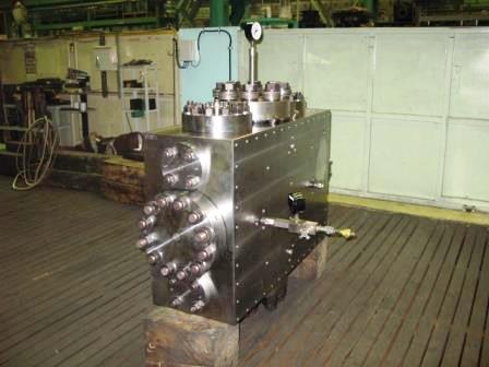
The cylinder shall be hydrostatically tested before installation of the cylinder liner. Besides, cylinder shall be tested with heads, valve covers, clearance pockets, and fasteners being already installed.
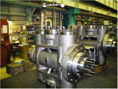
The filters and pressure vessel generally are manufactured at pressure vessel manufacturers and are tested there, So, it might not be necessary to subject them to hydrostatic testing at the compressor manufacturer facility.
The hydrostatic testing shall be done by calibrated pressure gage, and the preferable range is two times of the test pressure but in no case shall be less than 1.5 times and more than 4 times of the pressure test.
Reciprocating Compressor Gas Leakage Test
The API 618, requires helium leak test if the "service gas" molar mass equal or less than 12 or "service gas" has a mol percentage of Hydrogen Sulfide (H2S) equal or more than 0.1%.This information can be found in reciprocating compressor datasheet.
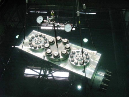
The helium leakage test shall be done after hydrostatic testing, and the test pressure shall be the same amount of compressor maximum allowable working pressure.

Similar to hydrostatic testing, the cylinder liner shall not be installed and shall be tested with the heads, valve covers, clearance pockets, and fasteners.
The pressurized compressor with helium at MAWP shall be submerged to the water pool, and the test result will be considered satisfactory if no bubble observed during the test (Zero Leakage). During the helium test, the internal pressure shall be maintained and recorded. The test shall be done based on manufacturer approved procedure.
The helium probe is the alternative test which can be done in lieu submergence test. The instrument sensitivity shall be agreed between compressor purchaser and manufacturer. Most of the manufacturers sue the submergence test.
Reciprocating Compressor Bar-Over Test
Reciprocating compressor bar-over test includes measurements of piston end clearance and piston rod vertical and horizontal runout measurement.
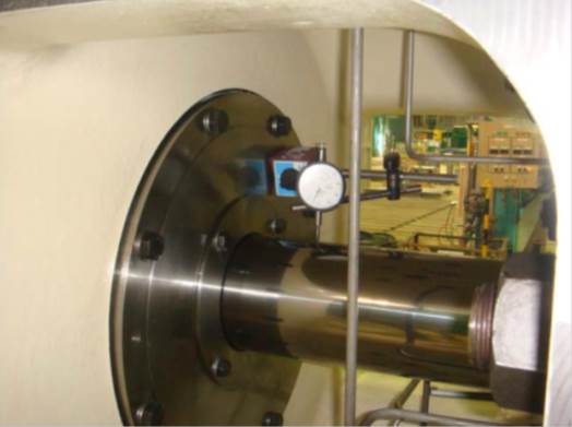
The test shall be done during the assembly and also after the mechanical running test which is called final bar-over test.
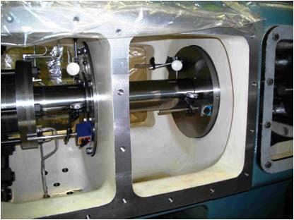
The piston end clearance is measured by feeler gage, and piston rod runout is measured by the dial indicator. The final bar-over test is one of the important test in the reciprocating compressor testing.
Piston End Clearance
The piston end clearance measurement shall be done during assembly and after the mechanical running test as a final bar-over test.
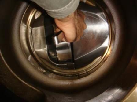
The clearance can be measured by inserting of filler gage or using a lead wire.
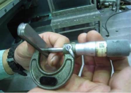
A lead wire is inserted from valve port, the compressor is turned and compresses the lead wire trapped between piston and cylinder. The compressor lead wire thickness can be measured and identify the piston end clearance.
Piston Rod Horizontal Runout Measurement
Similarly, the piston rod horizontal runout shall be performed during the assembly and also after the mechanical running test at the bar-over test. The runout test indicates the piston rod sagging amount. Dial gage is installed on the horizontal side of the piston rod, and then the compressor is turned, and the piston rod is moved from crank-end to head-end.
Then the dial gage indication is recorded and is checked against acceptance criteria. As per API 618, the horizontal piston rod runout shall not be plus or minus 0.00015 mm/mm (0.00015 in./in.) of stroke value (±0.015% of stroke value) but in no case shall be more than 0.064 mm or 0.0025 in.
Piston Rod Vertical Runout Measurement
Similarly, the runout is measured by the dial indicator. The dial indicator is mounted in verticle side of the piston rod (top of piston rod), the compressor turned, and the piston rod is moved from one end to other end, and the amount of runout is measured and recorded. As per API 618, the vertical runout shall not be more than plus or minus of 0.015% of stroke value.
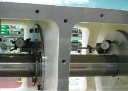
You need manufacturing drawing to be able to witness this test. You need to have stroke value and make a simple calculation and obtain maximum allowed values and then compare measured runout with your calculated values.
Reciprocating Compressor Vibration Analysis and Testing
The API 618, requires following vibration limits at compressor skid, cylinder, distance pieces, crankcase and cylinder flange pressure pulsation vibration. The vibration testing is one of important item in reciprocating compressor testing that is performed in mechanical running test part.
Vibration Limit @ Compressor Skid
The manufacturer shall make analysis and determine whether the vibration frequency is going to be less than 10 Hz or higher than 10 Hz. The manufacturer makes the calculation for vibration that comes from natural frequency of base plate and also significant excitation frequencies.
If the analysis indicates the vibration frequency is going to be less than 10 Hz, then magnitude of vibration shall not be more than 4 mil 0 to peak value or 8 mil peak to peak value.
If analysis indicates the vibration frequency is going to be higher than 10 Hz, then magnitude of vibration shall not be more than 4.5 mm/s RMS value (0.175 in/s RMS)

As you see, we are using displacement vibration probe (sensor) when vibration frequency is less than 10 Hz and using velocity vibration probe (sensor) when vibration frequency is higher than 10 Hz.
The API 618, requires that the reciprocating compressor manufacturer makes necessary calculations and provide the vibration limits for the cylinder, distance pieces, and crankcase. These amounts normally are indicated in approved mechanical running test procedure. The vibration testing is done in 4 hour mechanical running test.
The API 618 also requires that cylinder flange pressure pulsation vibration shall not be more than of 7% of average absolute line pressure or 3R% whichever is lesser. (the R is the stage pressure ratio). The vibration amplitude should be measured by displacement probe (proximitor sensor).
The standard also provides the piping system vibration limit. The limit is 0.5 mm peak to peak or 20 mil peak to peak when vibration frequency is less than 10 Hz. The limit is 32mm/s peak to peak or 1.25 in/s peak to peak when vibration frequency is 10 thru 100 Hz.
The third party inspection for reciprocating compressor article provides a sample inspection instruction for inspection. You may also need to review a sample recirocating inspection and test plan.
Following content provides some other information about reciprocating compressor testing:
Applicable Standards @ Reciprocating Compressor Testing
The applicable standards for these tests are:
- API Standard 618; reciprocating Compressor for Petroleum, Chemical and Gas Service Industries
- ASME PTC 10; Performance Test Code on Compressors and Exhausters
- BS EN ISO 5167-2; Measurement of fluid flow by means of pressure differential devices inserted in circular cross-section conduits running full - Part 2: Orifice plates
- BS ISO 5389 Turbo compressors Performance Test Code
Mechanical Running Test @ Reciprocating Compressor Testing
The following components are used from Job equipment
- Compressor main unit
- Lube oil unit
The following components are used from test stand
- Motor
- Pressure gauge
- Temperature gauge
The following components are not used in the test
- Suction/Discharge Valves
- Surge Drum
- Gas Piping
- Drum/Piping Support
- Instrument
The compressor is assembled in test stand in manufacturer's shop. The the cylinder valves would not be installed to perform non-load continuous operation.
The compressor is operated at the specified rotating speed for 4 hours continuously and mechanical stability, temperature, pressure, vibration and noise are checked.
After 4 hours continuous operation the reciprocating compressor needs to be stopped and bearing temperatures to be measured.
Then the reciprocating compressor is diassmbled and strip down inspection is done based the requirement of inspection and test plan.
Measurement items during Mechanical running test
Rotating Speed @ Reciprocating Compressor Testing
The rotating speed is measured by a tachometer every 30 minutes. The measurement value to be an average value of those indicated by the tachometer.
Rotating speed need to be be within of the specified rotating speed.
Oil Temperature @ Reciprocating Compressor Testing
The supplied and discharged oil temperature of crankcase is measured by temperature gauges in the shop lube oil unit every 30 minutes.
The supplied and discharged oil temperature needs to be within specified values.
Oil Pressure @ Reciprocating Compressor Testing
The supplied oil pressure of crankcase (bearings)and discharged oil pressure of lube oil pump are measured by pressure gauges in oil unit every 30 minutes.
The obtained values need to be in within specified values
.Vibration @ Reciprocating Compressor Testing
The vertical and horizontal vibrations of crankcase are measured at two locations by the use of a shop vibration meter. Also, the vibration at cylinder is measured with respect toaxial, horizontal and vertical directions by the use of a shop vibration meter. Vibration measurement needs to be done once during test operation.
The vibration of crankcase (peak to peak) needs to be within specified values.
Noise @ Reciprocating Compressor Testing
The noise is measured at a distance of 1 m from the side of the main unit and four directions by using a shop noise meter. Noise measurement to be done once during test operation.
The obtained noise value need to be within specified value.
Bearing Temperature Measurement @ Reciprocating Compressor Testing
The temperature for each of following bearings during the 4-hour continuous test operation needs to be measured periodically.
- Temperature of main bearing
- Temperature of crank pin bearing
- Temperature of cross head pin
The measured values need to be within specified values.
Lube Oil Console Running Test @ Reciprocating Compressor Testing
After completion of successful oil flushing the lube oil console running test needs to be done. Running test would be performed based on the following conditions for 4 hours, and temperature and pressure shall be measured every 30 minutes.
- Oil grade as per design
- Lube oil pressure as per design
- Lube oil temp as per design
- Motor speed as per design
- Start up as per design (generally cold condition)
No leakage must be seen during the test and Pressure drop of filter element shall not exceed a specified value at operating oil temperature. No abnormal sound shall be confirmed during the running test.
Tempered Cooling Water Console Running Test @ Reciprocating Compressor Testing
After completion of successful cooling water flushing the tempered cooling water system running test needs to be done. Running test would be performed based on the following conditions for 4 hours, and temperature and pressure shall be measured every 30 minutes.
- Fluid as per design (water with inhibitor or etc.)
- Pressure as per design
- Temperature as per design
- Motor speed as per design
No leakage must be seen during the test and no abnormal Pressure drop must be confirmed. No abnormal sound shall be confirmed during the running test.
After checking of the above items at two times, the water pump is changed to another and the same items needs to be checked.
Thermodynamic
Performance Test @ Reciprocating Compressor Testing
The reciprocating Compressor thermodynamic performance test is
similar to the centrifugal compressor. You may review Centrigugal Compressor
Testing for detail test instruction.
Following data need to be extracted from a centrifugal compressor design book, datasheet and operating manual and to be available during the test.
Specified Operating Speeds
- Normal Operating Spee
- Minimum Operating Speed
- Maximum Continuous Speed
- Trip Speed
Maximum Shaft Vibration
- At Maximum Continuous Speed
- At Trip Speed
Lube Oil Data
- Oil Viscosity Class
- Oil Inlet Temperature
- Oil Inlet Pressure
- Maximum Oil Volume Flow Of Compressor
Shaft Seals
- Seal Type
- Seal Medium