Watch our Most Recent Videos | Visit us on LinkedIn | Visit us on YouTube
Centrifugal Pump Performance Test
The centrifugal pump performance test is conducted by pump manufacturer after completion of the assembly to prove the pump has the required specification as indicated in the pump datasheet and other purchase documents.
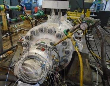
The performance test is conducted after completion of casing inspection, casing hydrostatic test, impeller, and rotor dynamic balancing. The NPSH test, mechanical running test, and final inspection are done after performance test. The vibration testing is carried out during performance test and mechanical running test. You may also want to review a general centrifugal pump inspection and test procedure.
Let explain the performance test by an example. You are attending to the pump manufacturer shop to witness a centrifugal pump performance test which is a hold point on the pump ITP. You review the pump approved datasheet and find following information:
Rate flow = 238.5 m³/h (1050.08 Gal/Min)
Rated Differential Head = 2690.28 m (8826.37 feet)
Rated Power = 2985 KW (4003 HP)
Rated Efficiency = 68 %
Upon completion of the centrifugal pump performance test, the pump manufacturer provides you following performance curve. You need to match this curve with datasheet specification to make sure the pump passed the performance test.
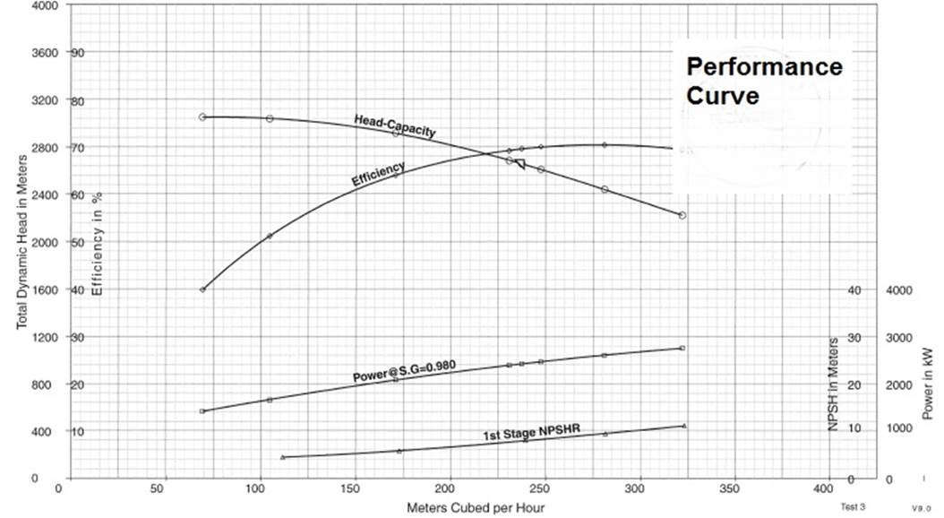
Let's start with head-capacity curve, we draw a verticle line at 238.5 (in the horizontal axis), and it will cross head-capacity curve, then we draw a horizontal line from the cross point, and it crosses the vertical axis at 2640. So the measured head at the 238.5 m³/h is 2640 meter.
What was expected value in the datasheet? It was 2690.28 m but the test result was 2640 m.
What is the test result ( the head almost is 50.28 meters less than required value)? The pump outperforming or underperforming?
The API 610 at table 18 says the head can be +/- 3% of the rated value. The 3 % of the rated value (2690.28 x 3%) would be 80.7 which is greater than 50.28, the pump underperforming but the test result is acceptable.
Let's assess the power consumption; we repeat the same process but this time with the power curve. The curve indicates the consumed power at 238.5 m³/h is 2600KW (power consumption was provided at the left side of the vertical axis). Compare 2600 KW with datasheet value which is 2985 KW.
Obviously, the pump outperforming since consumes less power. However, API 610 acceptance range is 4% it means the pump test result would be satisfactory even if consumes more than 4 % from what indicated in the datasheet.
We also need to check the efficiency. The minimum efficiency in the approved datasheet is 68 %. Check the efficiency curve, the efficiency amount at the 238.5 m³/h is 70%. So the pump is outperforming and gives higher efficiency than what required in the datasheet.
So the result of the centrifugal pump performance test for the differential head, power consumption, and efficiency is satisfactory.
The head value also shall be checked in shut off point but since this pump is high energy pump, the centrifugal pump performance test at the shut-off point (no flow at discharge valve) is not a requirement based on API 610.
The above example was a simplified example. The pump manufacturers usually provide a tabulated format to make it easy for review.
The manufacturers also simulate the test result to actual field condition. The pump might be designed for crude oil, but in the shop will be tested by the water. In such cases, the attained values will be converted to field condition by engineering calculation.
Subsequently, you need to check bearing housing and shaft vibration FFT spectrum (Plot) at each data point from minimum to maximum flow to ensure the vibration values are within acceptance range.
The Pump NPSH Test (Net Positive Suction Heat Test) report also shall be verified against approved datasheet values.
The pump mechanical running test is performed after successful completion of performance and NPSH test.
Now let deepen in the centrifugal pump performance test by the understanding of flowrate, total head, power, and efficiency.
What is the Flowrate and Head in Centrifugal Pump Performance Test?
Volume flow rate (Q), also referred to as capacity, is the volume of liquid that travels through the pump in a given time (measured in gallons per minute or GPM).
It defines the rate at which a pump can push fluid through the system. Flowrate is the first parameter specified by the process designer, who determines the pump requirement on the flowrate that the process needs to function.
This 'rated' flowrate is normally expressed in volume terms, and it is represented by the symbol q, with units of cubic meters/ second or GPM.
The static head of a pump is the maximum height (pressure) it can deliver. The capability of the pump at a certain RPM can be obtained from its Q-H curve.
The pump manufacturers are interested in providing pump performance curve in a way that does not depend on to the pumped fluid physical properties.
That is why they are using head instead of pressure. The following formula converts pressure to the head; H(meter) = 10.2 P/SG or H(feet)= 2.3P/SG
Once the rated flowrate has been determined, the designer subsequently specifies the total head (H) needed at this flowrate.
This is expressed in meter or feet and represents the usable mechanical work transmitted to the fluid by the pump. Together q and H define the duty point.
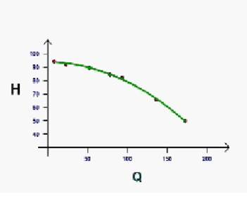
The q/H Curve Test;
The test is carried out at a nominally constant shaft speed, and the head (H) decreases as flowrate (q) increases, giving a negative slope to the curve. (See above H-Q curve)
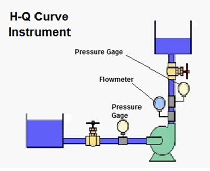
Look at the following sketch; this illustrates a simple H-Q curve loop. The test engineer changes the flowrate through discharge control valve and takes measurement of different variables and calculates the corresponding head.
The first set of measurements is taken at duty point (100 percent q). The valve is opened to give a flowrate greater than the duty flow (normally 120 or 130 percent q), and further readings are taken.
The valve is then closed in a series of steps, progressively decreasing the flow (note that we are moving from right to left on the Q-H curve). With some pumps, the final reading can be taken with the valve closed, i.e. the q = 0 or shut-off condition.
Once the test points are obtained, you can now check against the acceptance criteria requirements
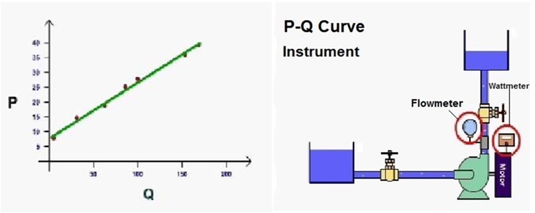
Power Consumption in Centrifugal Pump Performance Test
The power consumption is measured at different flowrates similarly, and the power-flowrate curve is plotted. A wattmeter is connected to motor power input, by multiplying wattmeter amount at motor efficiency the motor output power is calculated at different flowrates. Through these corresponding readings, the power-flowrate curve is plotted.
The Efficiency-Flowrate Curve at Centrifugal Pump Performance Test
The efficiency-flowrate (ƞ-Q) curve can be plotted based on measured values from combination of H-q curve and P-q curve and this formula ƞ=(P out of Pump)/(P input of Pump)=ρgHQ/(P input of pump) (ρ is density, g is gravitational acceleration, H is Head and Q is Flowrate)
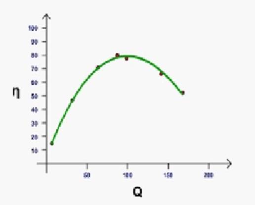
Pump efficiency (ƞ percent): the efficiency is the ratio of transferred mechanical work of the fluid to consumed power (P) in watts by the pump.
The efficiency test; the efficiency is checked using the same set of test measurements as the q/H test. Pump efficiency is plotted against q in above figure.
You may also review third party inspection for centrifugal pump and pump inspection and test plan articles as supplementary information.
This content
provides you with a sample Centrifugal Pump Performance Test Procedure in the manufacturing shop. The procedure is very brief and general.
Centrifugal Pump Performance Test Procedure
1.Scope
This description of procedure defines the conditions for the hydraulic testing of centrifugal pumps according to API Standard 610.
Scope of test, type of test, test class and guarantee values are defined by standardized test plans agreed between pump manufacturer and pump purchaser.
2. Objective
Objective of the tests is the continuous control of performance data as process control, keeping the guarantees given according to the supply agreement, testing of relevant pump functions.
Preparation of test reports and test curves according to the supply agreement as integral part of the test documentation.
3. Standards and Other
Regulations Applicable
- API 610
- Manufacture Standard
4. Centrifugal Pump Performance Test procedure
4.1 Testing Personnel
For the handling of the test beds, only trained personnel is employed. The setting of test data is done semi-automatically and requires appropriate test experience and accuracy.
4.2 Place and Time Of Testing
The testing is done on the test bay of the manufacturer. Only pure cold water with a density of ρ= 1 kg/dm3 is used as the test medium.
Pump block units are normally tested with installed motor. In case of acceptance by the customer, the readiness for the acceptance inspection is notified in time to the sales departments.
4.3 Pump Test Beds
Both of following test beds are available and will be utilized as per purchase order specification
- Closed System
- Open System, Alternatively With Booster Pump
4.4 Measurement And Testing Methods
The measurement and evaluation of hydraulic characteristic values is made by means of an electronic data logger.
All relevant data are recorded at the site by means of electronic measuring devices and presented with online electronic data processing at the test sites. After termination of the measurements, the data is transferred to the central computer of the test bay supervision. Unless otherwise specified, the acceptance performance tests are carried out in acc. with API 610, para. 7.3.3.
4.4.1 Measurements Of Flow Rate Q
The flow rate is measured using magnetic inductive flow measuring devices having the specified stabilization distances in front and after the measuring unit. The setting of the capacity is effected by control valves in the discharge pipe.
4.4.2 Measurement of head H (Hd - Hs)
Pressure measurements are made using calibrated measuring transmitters for the measuring point Hs (measuring range -10 up to +40 m wc), for measuring point Hd (measuring range -10 up to +180 m, 150 up to 630 m wc). For visual comparison, calibrated spring manometers are connected in parallel for analogous display.
4.4.3 Measurement of Velocity Head
The velocity head is calculated using the flow rate and the flow cross-section at the pressure measuring point.
Vd = velocity discharge side
Vs = velocity suction side
Δ = velocity difference between suction and discharge side
4.4.4 Measurement of power input (P)
The power input of the pump is determined either electrically by means of a calibrated test motor or by directly measuring the speed of rotation using a torque measuring hub.
The electrical measurement is made according to the two-watt meter method for determining the motor power input. The motor power output is calculated using the motor efficiency curve stored in the test system.
For comparison of guaranteed data, the test system converts the pump power input required for the customer conditions, i.e to the standardized speed and the density of the acually pumped medium.
4.4.5 Measurement Of Speed (n)
The speed measurment occurs by means of a light barrier or photo sensor. For canned motor pumps, not accessible from the outside, the speed is determined by means of a bend coil or by frequency analysis.
4.4.6 Measurement of Pump Effeciency (η)
The pump efficiency is determined for each measuring point immediately following the measurement by the testing system.
According to the following formula:
Flow rate Q [m³/h]
Head H [m]
Density ρ [kg/dm3] of pumped medium
Power P [kW]
4.4.7 Measurement of the NPSH value of the pump (NPSH required)
Normally in the closed circuit, the measurement of the NPSH value is made by reducing the system pressure by means of a vacuum pump. Measurement also is done by throttling using a throttle valve in the suction line, as the case may be.
Reaching the guaranteed value at the required NPSH value can be proven using the following 2 measuring methods.
a) Standard
Proof of reaching the required NPSH value by setting the peripheral conditions which are equal inthe system such as flow rate, head when reducing the suction pressure depending on the water temperature and the barometric level.
Comparison of head, taken from the characteristic curve measurement above, with the head measured at actual suction negative pressure where the guaranteed NPSH value is achieved or is not achieved.
The head decrease may not exceed 3 % of H, but does not have to achieve 3 % (for single-stage pumps).
According to the specifications in the order, 1 or 3 to 5 measuring points are used. For 2 stage pumps, the max head decrease may not be ΔH≤1.5 %
So NPSH test for multi stage pump is not possible.
b) Optional as Head Breakdown Curve
Proof of the min. achievable NPSH value at a specific constant flow. By reducing the suctionhead, starting at NPSH = 40 m, a number of measuring points (8-12) are recorded until the pumping breaks down. The cut-off point at 3 % head decrease since the beginning of the measurement results in the cavitation condition of the pump at this point and is defined in the applicable standards as NPSH required (for 2 stage pumps 1.5% ΔH)
Reference level for calculation of the NPSH
a) Horizontal Pumps
Horizontal level through the shaft axis
b) Vertical Pumps
Plane surface vertical to shaft axis at impeller inlet
Calculation of The NPSH Based on The Measured or Known Parameters:
The calculation of the NPSH value occurs simultaneously with the measurement.
The following parameters are required for this:
Suction head
Water temperature
Steam pressure of water(absolute vaporization pressure)
Atmospheric pressure (absolute)
Atmospheric height (absolute)
Distance reference level/measurement level
Speed at suction side
Density of test field water
Acceleration due to gravity
The NPSH is calculated according to the following formula:
The conversion of the NPSH value from the measured speed to the nominal speed is made according to the following formula (only valid for the speed range ± 3 %):
4.4.8 Additional Measurements
Upon request, the electrical current I [A] and the voltage U [V] can also be measured.
4.5 Number of measuring points
The number of measuring points for the pump characteristic curve or NPSH measurements must
be agreed in the supply agreement.
Characteristic curve at 0, Qmin, Qmean, Qnom, Q120%, standard measurement of 5 points (9 max.)
NPSH measurement 0, Qmin, Qmean, Qnom, Q120% 4 points (7 max.)
5 Centrifugal Pump Performance Test - Guarantees
The rated values of the pump are guaranteed in compliance with API 610 provided that no other customer requirements exist. The measuring of tolerances is done automatically by the measuring system.
For viscous media, only the specified data for cold water is guaranteed. The results with viscosity will be shown for information as conversion curves according to Hydraulic Institute.
6 Centrifugal Pump Performance Test - Vibration measurement
To assess the mechanical and hydraulic operating behavior of the pump tested, vibrations are recorded at the same time as the hydraulic date (min. 5 points).
Measurement is carried out in three planes - horizontal, vertical and axial - by means of vibration pick-ups fitted on the bearing bracket. The measureng criterion is the root mean square velocity of all vibrations determined (vibration velocity RMS in mm/s).
The limit stipulated by API 610 is for horizontal pumps 3 mm/s in the preferred operating range of the pump. In the allowable operating range, a vibration velocity of up to 3.9 mm/s (max.) is permissible. For vertical pumps the limit 5 mm/s in the preferred range and 6,5 mm/s in the allowable range is applicable.
Alternatively, it is also possible to measure the max. vibration amplitude (peak-to-peak).
Horizontal
Limit in preferred range: 2,0 mils (50 μm)
Limit in allowable range: 2,6 mils (65 μm)
Vertical
4,0 mils (100 μm)
5,2 mils (130 μm)
The frequency spectrum (FFT analysis) can be measured, if requested.
7 Centrifugal Pump Performance Test - Measurement of Bearing Temperature
If required, the measurement of the bearing temperature will be performed for a specified operating time. The measurement is taken on the bearing bracket on the outside at the level and position of the pump side or motor side bearing in horizontal direction.
8 Centrifugal Pump Performance Test report
The test results are stored in the central computer of the test bay supervision and on other electronic data carriers. Upon request, test reports and test curves are prepared for the customer.
Free newsletter!
Sign up to receive my monthly newsletter covering all the latest courses and updates.
FIND US HERE:


Copyright © 2012-2024 Inspection 4 Industry LLC
Contact Inspection 4 Industry by Email
Contact by Phone - 949-383-0564
New! Comments
Have your say about what you just read! Leave me a comment in the box below.