Watch our Most Recent Videos | Visit us on LinkedIn | Visit us on YouTube
Pump Impeller Dynamic Balancing
The pump impeller dynamic balancing is done based on API 610 requirements. The standard requires the balancing be performed based on ISO 1940-1 to the Grade G2.5
Some calculation needed to be performed to determine the acceptance criteria, but these are done by pump manufacturer design engineer. The inspector shall verify the approved balancing test procedure and identify following information:
- Is it the single plane or Double plane balancing?
- Arbour Speed (RPM)?
- Acceptance Criteria?
With above information, you will be able to witness the test and verify test report. Let's start with an example.
Example for Pump Impeller Dynamic Balancing

You are attending to the pump manufacturer to witness an impeller dynamic balancing test. You review approved test procedure and find the following information.
- It is Double Plane Balancing
- The Arbour Speed is 1800 RPM (the impeller mounted in the Arbour)
- Acceptance Criteria is 0.001 oz-in
The balancing technician mounts the impeller in the arbour and place them on the balancing machine. The machine starts running and spinning the impeller at 1800 RPM. (Revelation per Minute)
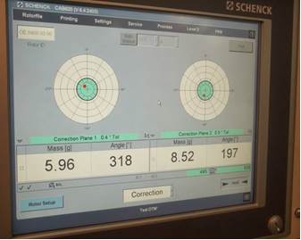
You see the following information on the screen:
Pump Impeller Dynamic Balancing - Runs
Run 1
Left -183 mg at 217° unbalance 367 mg-in (0.0129 oz-in)
Right -190 mg at 295° unbalance 286 mg-in (0.0100 oz-in)
As you see, the amount of unbalance in both left and right planes are more than acceptance unbalance value (0.001 oz-in)
So the technician works on the impeller by grinding and removing some weight from certain area to reach the amount of unbalance to the 0.001 oz-in
He stops grinding and runs the machine to measure the amount of unbalance. The result is as following:
Run 2
Left -146 mg at 216° unbalance 292 mg-in (0.0103 oz-in)
Right -134 mg at 297° unbalance 201 mg-in (0.0070 oz-in)
As you see in the run 2, the amount of unbalance reduced but still is not meeting the acceptance criteria. These values shall be reduced to the 0.001 oz-in
The technician continues working on the grinding and balancing the impeller and run the machine several times and collects the data. See following for final run.
Run 10
Left -7.32 mg at 296° unbalance 14.6 mg-in (0.00051 oz-in)
Right -10.7 mg at 75° unbalance 16.0 mg-in (0.00056 oz-in)
So this time the amount of unbalance in both planes are less than 0.001 oz-in and pump impeller dynamic balancing can be approved.
Now let see how pump design engineer calculates the acceptance criteria (the permissible unbalance amount)
Permissible Unbalance (g-mm) = (1000 x balance grade value x weight of impeller in (Kg)/ angular velocity (rad/S)
For example, if you have an impeller with 2 Kg weight and with rotor rpm of 3000 RPM, then permissible unbalance will be as following:
Permissible Unbalance = (1000 x 2.5 x 2) / 314.2 = 15.91 g-mm ( 0.022 oz-in)
The 2.5 is the "grade of balance" is taken from ISO 1940-1 and required by API 610 to be 2.5. The unit for 2.5 is mm/s
The 314.2 is angular velocity of shaft speed. We divided 3000 RPM to 9.54 to obtain speed in rad/s
The inspector does not need to perform this calculation since the calculated value is provided in the approved procedure.
Free newsletter!
Sign up to receive my monthly newsletter covering all the latest courses and updates.


New! Comments
Have your say about what you just read! Leave me a comment in the box below.