Heat Exchanger Inspection
The Heat Exchanger Inspection article provides you with information about the inspection of the heat exchanger and heat exchanger testing during the manufacturing phase, as well as in-service inspection in operating units. You may want to review shell and tube heat exchanger inspection procedure and related inspection and test plan.
Heat Exchanger Inspection requirement is covered in the API 510 pressure vessel inspector training course. A detailed discussion of the different types is addressed in API RP 572, which is part of this training course. The manufacturing inspection is done based on ASME VIII Div.1, ASME IX, and ASME V and is covered by the I4I Academy ASME Training course.
Shell and Tube Heat Exchanger Inspection in Manufacturing Shop

The construction code for shell and tube heat exchangers is ASME Code Section VIII, and it covers the minimum requirements for design, materials, fabrication, inspection, testing, and preparation for initial delivery.
After the 2003 addenda of ASME Code Section VIII Div. 1, the design of the shell and tube heat exchanger needs to be done based on Subsection C, in UHX part. The design based on TEMA, or any similar code might be accepted which meeting the requirements of UHX part.
The heat exchanger still is a pressure vessel and all requirements for ASME pressure vessel does apply for heat exchanger as well. We are going to avoid to repeat those requirements for the heat exchanger. You may review pressure vessel inspection article for those requirements.
There are several inspection requirements that only apply to the heat exchanger and not regular pressure vessel:
Tube Inspection
The tube outside diameter, inside diameter, thickness, and ovality shall be checked before the building of the tube bundle. You need to refer to ASME Section II to get the acceptance tolerances.
For example, if your tube material is SA 179, you have to refer to the SA 179 and that will refer you to the SA 450 ( Specification for General Requirements for Carbon, Ferritic Alloy, and Austenitic Alloy Steel Tubes) for acceptance tolerance. You have to use your caliper, machinist ruler, etc. to make these measurements and make sure the values fall within acceptance range.
Tube Bundle Inspection
The bundle dimension shall be checked based on the approved drawing. The baffle diameter and distance between them shall be controlled and meet the acceptance tolerances in the drawing.
The tightness of stay bolts and spacers must be controlled. The shell cleanliness needs to be verified and make sure the inside welds are complete and are ground as per drawing requirements.
Tubesheet Inspection
The Tubesheet shall be inspected before welding to the shell. The hole diameter, grooves dimensions, drilling pattern, the thickness of the tubesheet and surface finish shall be measured and checked aginst acceptance tolerances in the approved drawing.
Tube Rolling Inspection
The tube rolling shall be checked based on customer specification. The wall reduction (after rolling) and depth of roll shall be measured and shall meet the customer specification. The wall reduction should not be less than 5% and should not be more than 8% of the tube wall thickness.
Leak Testing of Seal Weld (Tube to Tubesheet)
If seal welding considered, then the leak test will be a mandatory requirement. The shell side will be subjected to the air pressure, and water and soap solution will be sprayed to the tubesheet to make sure all seal welds are defect free. The bubble will be developed if there was any welding defect such as crack, pinhole, etc.
Shell side Hydrostatic Testing
After manufacturing completion, the heat exchange shell side will be subjected to the hydrostatic testing. The test pressure amount shall be consistent with the value indicated in the approved drawing. The holding time shall be based on the supplier approved test procedure.
The pressure gages calibration and range shall be controlled. The pressure gage range shall be within 1.5 thru 4 times of test pressure. The shell body and welding seams shall be inspected. The tubesheet also shall be checked. No leakage is allowed.
The test pump hose shall be disconnected, and no pressure drop is allowed. The test result will be satisfactory if no leakage being observed and no pressure being dropped while the shell side was under pressure.
Tubeside Hydrostatic Testing
After successful completion of shell side hydrostatic testing, the bonnets are assembled, and tube side is subjected to hydrostatic testing. Similarly, the amount of test pressure shall be as the one indicated in the approved drawing. Other requirement is similar to the shell test. No leakage and pressure drop shall be observed while the tube side is under pressure.
Third Party Inspection for Shell and Tube Heat Exchanger article provides you a procedural content for heat exchanger inspection. Review following standard Inspection and Test Plan for Shell and Tube Heat Exchanger.
You might be interested in reviewing following related articles:
Fin Tube Heat Exchanger Inspection
Third Party Inspection for Fin Tube Heat Exchanger
Inspection and Test Plan for Fin Tube Heat Exchanger
Shell and Tube Heat Exchanger Application
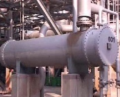
Shell and Tube heat exchangers are the most popular type in the industry. This type is made from 3 components as listed below:
- Two heads (one rear head, and the other one stationary head)
- Shell
- Tube
One fluid is in the tube side and the other one in the shell side. The heat transfer is done through the tube wall.
So your heat exchanger with more tubes will have more heat transfer surfaces, and at the same time will have a higher heat exchanger diameter.
There are different kinds of shell and tube heat exchangers with different applications.The reason for the high amount of applications is that they are easy to maintain.
Besides, the shell and tube heat exchanger is the only type that can be designed and operated at a temperature greater than 360 degrees centigrade, as well as in pressure higher than 30 bar.
In-Service Inspection of Shell and Tube Heat Exchanger
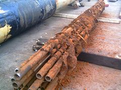
The In-Service Inspection code for shell and tube heat exchangers is API STD 510. The other API recommended practices and codes also have to be used in with this Code.
Some of these Recommended Practices are API RP 572, API RP 577, and API RP 571, and also construction code sections might be used, such as ASME Code Section VIII and ASME Code Section IX.
For repair, the requirement of API STD 510 or ASME-PCC-2 needs to be met. The title of ASME-PCC-2, which was first published in 2006, is: “Repair of Pressure Equipment and Piping.”
Please note: if your shell and tube heat exchanger is “U” stamped and you need to do the repair, you have to use a Repair Organization holding an “R” Stamp from the National Board Inspection Code.
The API 510 Pressure Vessel Inspectors are qualified persons to perform shell and tube heat Exchanger inspection. You may also review the Industrial Plant Inspection article.
What are the Important Items in the Shell and Tube Heat Exchanger Inspection in Overhaul?
Shell and Tube Heat Exchanger Inspections are categorized in the following way:
Shell and Structure in Heat Exchanger Inspection
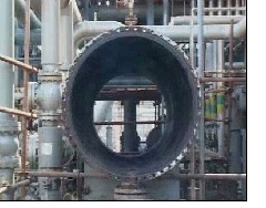
- Neutralization of Austenitic Stainless Steel shell, clads, liner or weld overlay, which contains H2S service. The process needs to be done based on approved procedures by a corrosion engineer.
- Neutralization is also required for shell material with admiralty brass to reduce the risk of SCC.
- Neutralization of thermocouples, if necessary, and doing dye penetration test
- Sampling from shell fouling and corrosion products and making lab analysis and making interpretation by corrosion engineer (if necessary)
- Cutting small area of insulation sheet and removing the insulation and doing visual inspection for any sign of corrosion under insulation
- Thickness measurement of different parts of shell and shell nozzles and making corrosion rate and remaining life calculation
- Inspection of shell cleaning and approval i.e. water jetting etc.
- Checking inside surface for any cladding, liner failure or separation
- Inspection of Shell flange gasket seating area for any erosion, damage and cracking
- Inspection of longitudinal and circumferential weld joints, inlet and outlet nozzles, reinforcement pads and small bore connections for any crack, corrosion and mechanical damage and deformation
- Dye penetration test on weld joints that are susceptible to cracking, austenitic flange face, weld overlay and cladding surface and exchangers exposed to amine and caustic
- Hydrogen blistering inspection in hydrogen services (hand lamp procedure)
- Heat exchanger support, steel structure, foundation, bolt and nut inspection
Bonnet in Heat Exchanger Inspection
- Thickness measurement and making corrosion rate and remaining life calculation
- Girth flange inspection for corrosion and erosion
- Internal surface inspection for corrosion and fouling
- Painting inspection of external surface
- Dye penetration or magnetic particle examination of weld joints susceptible to cracking
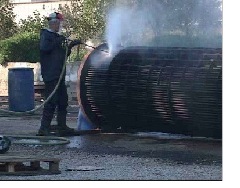
Tube Bundle in Heat Exchanger Inspection
- Taking care in the pulling out of tube bundle to avoid any mechanical damage
- Sampling from tube side fouling and corrosion products and making lab analysis and making interpretation by corrosion engineer (if necessary)
- Controlling of water jetting or lancing cleaning process
- Controlling wire brushing process of inner tube edge and rolling area (preparation for ID measurement)
- Inside diameter measurement in tubes and tubes rolling areas
- Rate off and accordingly plugging the tubes when their OD reaches to the ID plus one thickness
- Retubing of tube bundle if more than 10% of tubes reach the above rejection limit
- Inspection from tube bundle components such as tubesheet, tube, tie rods and spacers, transfer baffles or support plate, impingement baffle, floating head flange and floating head backing device
- Inspection from internal surface of tubes for corrosion and fouling
- Pulling out a sample tube for sectioning and corrosion anlaysis if necessary
- Retubing when sectioning result proves the thickness is half of the nominal value
- Visual inspection and dye penetration test from tube to tubesheet seal or strength weld
- Eddy current testing if it is necessary
Channel in Heat Exchanger Inspection
- Thickness measurement and making corrosion rate and remaining life calculation
- Inspection of gasket seating area, pass partition and nubbing for corrosion and deformation
- Inspection of internal surface for fouling, corrosion and soundness of linings (if any)
- Balance hole inspection for corrosion and erosion
- Welding joints inspection for any possible cracks
- Reinforcement pad inspection and doing soap test if necessary
- Cathodic protection anodes inspection and replacement if necessary
- Diaphragm and division box visual inspection and dye penetration test of diaphragm for any possible cracks (for high pressure exchangers)
Channel Cover in Heat Exchanger Inspection
- Thickness measurement and making corrosion rate and remaining life calculation
- Inspection of gasket seating area for corrosion and deformation
- Inspection for internal surface for fouling, liner, cladding and coating soundness
- Soap test in channel cover with liner
- Lifting lug weld joint inspection for any possible crack
Floating Head Inspection:
- Thickness measurement and making corrosion rate and remaining life calculation
- Inspection of gasket seating area, pass partition and nubbing for any possible corrosion and deformation
- Girth flange weld joint inspection for any possible crack and corrosion
- Internal surface inspection for corrosion and fouling and soundness of liner, coating and cladding (if any)
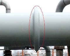
Expansion Joint Inspection
- The heat exchangers with expansion joints need to be inspected for:
- Flange inspections for corrosion and erosion
- Inspection from internal surface for corrosion and erosion
- Air test
- The tube and shell hydrostatic test need to be done after the above stated inspection activities.
Free newsletter!
Sign up to receive my monthly newsletter covering all the latest courses and updates.


New! Comments
Have your say about what you just read! Leave me a comment in the box below.