What is the Welding Map?
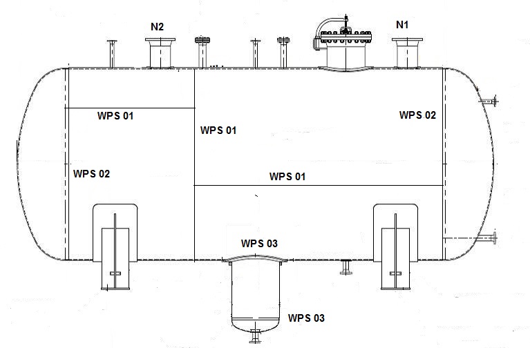
The welding map is the equipment sketch which identifies the welding seams and indicates what welding procedure specification (WPS) shall be used for that particular welding seam.
The subject of weld maps is included in the I4I Academy API Source Inspector Fixed Equipment Course.
The welding procedure specifications (WPS's) are provided by the manufacturer to the customer for approval. The weld procedures provided to customer alongside vessel or equipment drawings and design calculation.
The customer welding SME (subject matter expert) reviews the welding procedures and comment or approve them.
A particular vessel or equipment might have several welding procedures for different locations. The welding map assists the project team, i.e., customer inspector, welding engineer, supplier quality control team, etc. to identify related weld procedure and correspondent weld seam.
Welding Map Example
The following sketch illustrates a typical pressure vessel weld map and indicates 4 WPS's are going to be used for manufacturing of this pressure vessel.

The WPS 01 will be used for longitudinal and circumferential joints.
The WPS 02 will be used for head to shell joints. In this vessel, the heads are torispherical, and the thickness of the heads are 1.7 times of the shell and WPS 01 can not be applied here since thickness range limitation.
The WPS 03 will be used for boot welds. The shell and head materials are carbon steel, and boot material is stainless steel so the WPS 01 and 02 can not be utilized for boot section since it has different P number.
Depends on the equipment design it might have several WPS's, and we need a map to show them in the drawing. The map also can be displayed in tabulated format. There is no standard form for weld map, and each manufacturer has own way to illustrate applied WPS's in the vessel/equipment drawing.
Free newsletter!
Sign up to receive my monthly newsletter covering all the latest courses and updates.


New! Comments
Have your say about what you just read! Leave me a comment in the box below.